- IDL 100%
| Filename | Latest commit message | Latest commit date |
|---|---|---|
| COMPOSITE_SCH.brd | ||
| COMPOSITE_SCH.lbr | ||
| COMPOSITE_SCH.pro | ||
| COMPOSITE_SCH.sch | ||
| eagle.epf | ||
| PCB.png | ||
| README.md | ||
| Schematic.png | ||
| template_2_layer.cam | ||



UniCVMod by El Dr. Gusman
This is a small circuit to convert RF output to composite video. It's a complete drop-in replacement for the astec RF modulators, just remove the old "can" and drop the circuit in it's place, as simple as that.
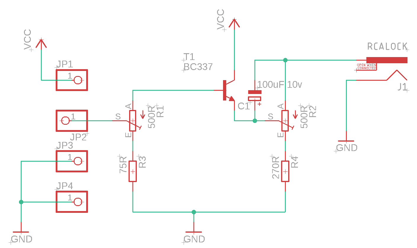
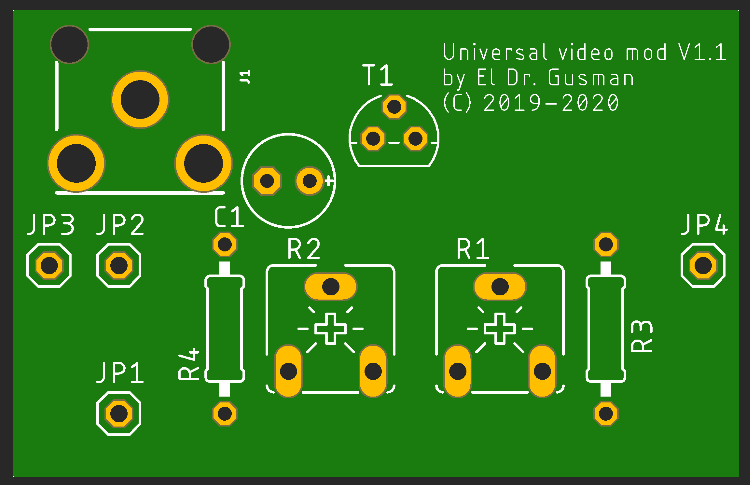
Update 1.1
Added capacitor on the output to improve video quality.
Assembly notes
JP3 and JP4 are intended to be pins on the under side of the circuit which will connect to ground and leave a bit of space between the device's board and the mod solders, they fit on the same place as the RF can has it's grounding legs. JP1 and JP2 are intended to be wired and use the inputs to the RF can.

As a final measure I use some small rubber feets under the front and back of the circuit to make it totally stable and avoid any chance of short circuit.
Calibration notes
R1 and R2 are 500Ohm potentiometers in order to allow you to adjust the signal level according to your needs, R1 will adjust the input level and R2 will adjust the output level. Composite video should have an amplitude of 0.7v but with modern TV's and converters sometimes more signal increase the picture quality, so adjust it at your will.
Part list
- R1, R2 - 500 Ohm trimmer
- R3 - 75 Ohm, 1/4w
- R4 - 270 Ohm, 1/4w
- C1 - 10uF 16v
- T1 - BC337
- JP3, JP4 - Single pin
- J1 - RCA female (RCA-103)